Poster Presentation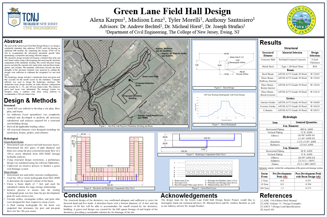 Figure 1: Poster Presentation Abstract
The goal of the Green Lane Field Hall Design Project is to design a sustainable dormitory that addresses TCNJ’s need for housing an additional 600 students. By completing this design, TCNJ will be able to accommodate the anticipated population growth while maintaining a sustainable and energy efficient campus. The structural design included developing a detailed floor plan and steel frame outline along with designing and analyzing the structural components of the dormitory building. The overall structural design process included the concrete slab, metal deck, roof and floor beams, girders, and columns. The moments, deflections, flexural and shear strengths of the structural elements were analyzed to confirm the designs were sufficient to withstand the designated live and dead loads. The hydrologic design included a storm water basin and green roof that accounts for the runoff caused by the dormitory. Computer software was used to design the hydrologic structures. The storm water basin design includes an outlet structure configuration that accounts for 2-, 10-, and 100-year storm events. The extensive green roof layers were determined. The drainage system was designed using a Siphonic roof drain sizing software to accommodate a 100-year storm event. Design and Methods Structural •AutoCAD was utilized to develop a site plan, floor plan, and frame. •An elaborate Excel spreadsheet was completely outlined and developed to perform all necessary calculations and analyses required for a structural steel building design. •Derived all applicable loading values. •All structural elements were designed including the metal deck, beams, girders, and columns. Hydrological Green Roof Design •Determined type of green roof and necessary layers. •Determined the first guess of pipe diameter and drain size using the post-construction peak flow of a 100-yr storm obtained from HEC-HMS through hydraulic analysis. •Using structural design restrictions, a preliminary design was simulated using the software Siphonitec. •Underwent an iterative process to finalize a green roof drainage system. Basin Design •Determined size and outlet structure configuration. •Used the 100-yr storm hydrograph from HEC-HMS to determine the required volume of the basin. •Chose a basin depth of 7 feet and used the calculated volume for stage-storage relationship. •Iterative process to ensure that the routing hydrograph peak was less than the pre-development peak for each storm event. •Circular orifice, rectangular orifice, and grate inlet were designed for their respective storm events. •A final routing hydrograph for the basin was outputted that attenuates the post and pre-peak flows for the 100-year storm. Conclusion The structural design of the dormitory was confirmed adequate and sufficient to resist the factored dead and live loads. A detention basin with a bottom diameter of 10 feet and top diameter of 40 feet will be able to accommodate the runoff created by the dormitory building. A green roof design was created for the full square footage of and height of the dormitory, providing a sustainable solution for the drainage of the site. Acknowledgments The design team for the Green Lane Field Hall Design Senior Project would like to thoroughly thank our technical advisors, Dr. Michael Horst and Dr. Andrew Bechtel, as well as our industry advisor Dr. Joseph Strafaci.
0 Comments
Structural Team UpdateThe structural design team, consisting of Alexa Karpus and Tyler Morelli, is in the final stages of completing the structural design of the Green Lane Field dormitory building. The design process consisted of the development of a detailed floorplan and steel frame outline in addition to a structural design and analysis spreadsheet. Prior to the iterative process of designing concrete slab, metal deck, beams, girders, and columns, it was necessary for the team to construct the steel frame and floor plan in order to properly identify all unique structural members and any applicable design dead and live loads. The finalized AutoCAD drawing of the floorplan with the placement of the columns, beams, and girders is outlined in figure 1. 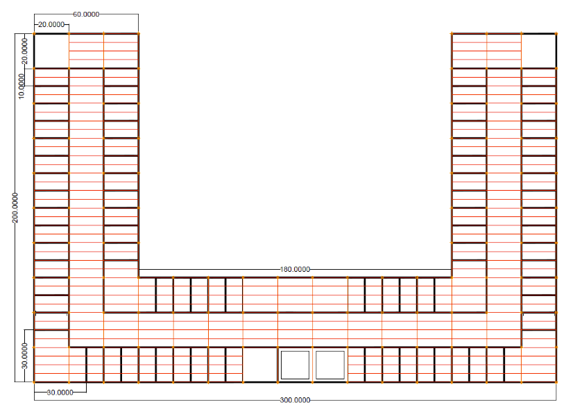 Figure 1: Finalized Floorplan and Steel Frame Plan of the Dormitory This floorplan represents where the columns, beams, and girders would be. After the frame plan was finalized, we were able to move onto the design work of the individual components. To design the individual components, we constructed an excel spreadsheet so it would be more efficient. We coded the spreadsheet to automatically update the entire design if something was altered. This made the design process easier. With this spreadsheet, we were able to design the slab, beams, shear connections, girders, and the columns. This is represented in figure 2. 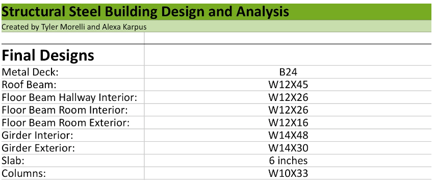 Figure 2: Table of the Design Selections For the next month, our goal is to calculate the horizontal loads due to the rain, wind, and snow. We will then need to analyze the designs and confirm they are sufficient. If they are not sufficient, we will be adjusting the designs accordingly. Water Resource TeamBasin Design The final design for the stormwater detention basin was completed using a computer software. The basin size was calculated and an outlet structure configuration was designed. The outlet structure includes designs for a 2-year, 10-year, and 100-year storm event. For the 2-year storm a circular orifice was designed, for the 10-year storm a rectangular orifice was designed, and for the 100-year storm a grate inlet was designed for the top of the rise box. Figure 3 shows the final hydrograph for a 100-year storm event with this design. Figure 4 shows the size and dimensions of the outlet structure configuration. The basin will have a top diameter of 40 feet and a bottom diameter of 10 feet with a depth of 7 feet, which is displayed in Figure 5. 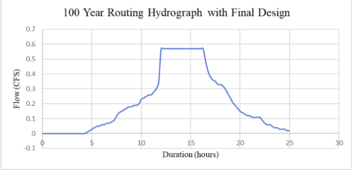 Figure 3: 100- Year Hydrograph for the Final Basin Design 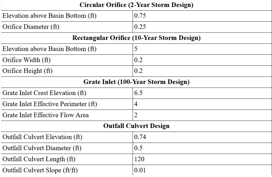 Figure 4: Table Showing the Outlet Structure Design Specifications for the Basin 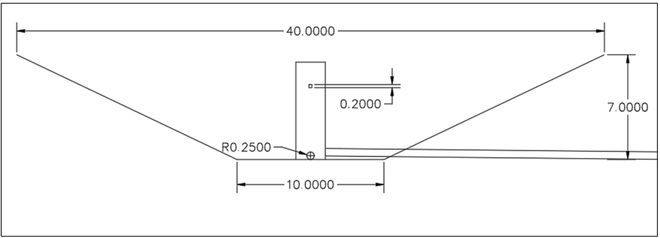 Figure 5: Cross-Section Layout of Storm Water Detention Basin Green Roof: The extensive green roof layers were designed as well as the green roof drainage system. The final configuration of the green roof consists of a combination of 8-inch and 3-inches pipes. The 8 inch parts consist of 460 feet of horizontal piping, 32 feet of vertical piping, four 90° elbows, one 45°elbow, one 8x8 45° junction, and two 8x3 reducers. The 3 inch parts consist of 60 feet of horizontal piping, 56 feet of vertical piping, four 90° elbows, two 3x3.1 1005T adapters, and two 3.1 JSR 1005T drains. All parts are made of cast iron (A888). Each drain is able to accommodate 17,400 square feet and the system can accommodate a peak flow of 1.9 cfs that was obtained from HEC-HMS. The total imbalance of the system is approximately 0.01% which provides insight on the accurateness of the system since the imbalance percentage cannot exceed 10%. Figure 6 represents the placement of the piping in the dormitory. 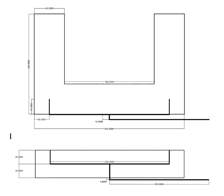 Figure 6: Location of the Pipes Structural Team UpdateThe structural team is currently prioritizing making the dormitory floor plan finalized and ensuring the column spacing and beam spans are adequate for design. In Figure 1 the floor plan with uniform column placement is outlined. The circles indicated on the floor plan represent the locations of the columns, which will be spaced 10 feet or 20 feet from one another to maintain a uniform and rectangular distribution of the columns. The total area of the dormitory will be exactly 27,000 square feet. Within each floor, the dormitory will accommodate 72 double-rooms and 2 quad-rooms, which will allow for 152 students to be housed per floor. To satisfy the projected increase of 660 students at The College of New Jersey, 5 floors will need to be installed, totaling 760 students for the entirety of the dormitory building. On each floor there will also be three designated stairways, with one at each end of the hallway, and one in the middle of the floor. Additionally, an elevator shaft with two elevators will run through each floor of the building, being placed next to the center stairway. Two communal bathrooms will also be installed at each corner on all floors. The designated additional space parallel to the elevators will either provide lounge space or an area for the lobby entrance for the ground level. 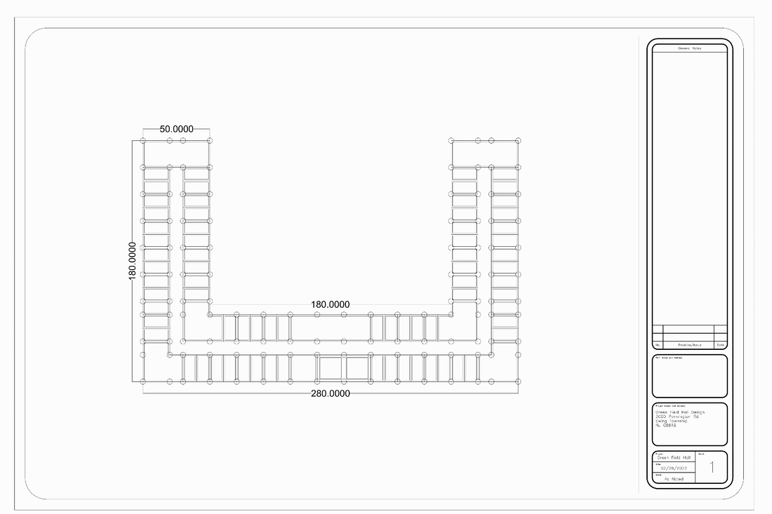 Figure 1: Frame and Floor Plan In addition to working on the structural frame and floor plans, the team has been intensely analyzing the ASCE manual to determine the necessary dead and live loads that will need to be considered within design calculations for the building. The structural team also utilized the AISC Steel Construction Manual to assist with determining what loads would need to be considered. Throughout the next month the structural team will finish the loading analysis and complete design of the deck, joists', beams, columns, slabs, and any bolt/welded connections needed. A proper structural analysis and design will be conducted to ensure that all designed elements, as well as the entirety of the dormitory design, complies with all design requirements and regulations defined by AISC, ASCE, and other necessary specifications. Water Resources Team UpdateThe water resources team is currently working on the basin design for the field as well as the green roof design where both will be designed for a 100 year storm. Research has been completed regarding the type of green roof that will be designed, concluding that an extensive green roof will be utilized. Madison has been using the software Siphonitec to aid in the design and calculations of the siphonic roof drainage system based on the specifics of the location and building geometry with the help of the International Plumbing Code and ASPE Technical Standards. Anthony has been using the program VT/PSUHM to design the basin for the field. The basin needs to account for the runoff caused by the dorm building. By inputting the storm hydrograph, as well as estimating the size of the discharge pipes and outlet culverts, a rating curve for the basin was generated, which is represented in figure 2. At this point in time, the basin characteristics are preliminary and adjustments may need to be made. 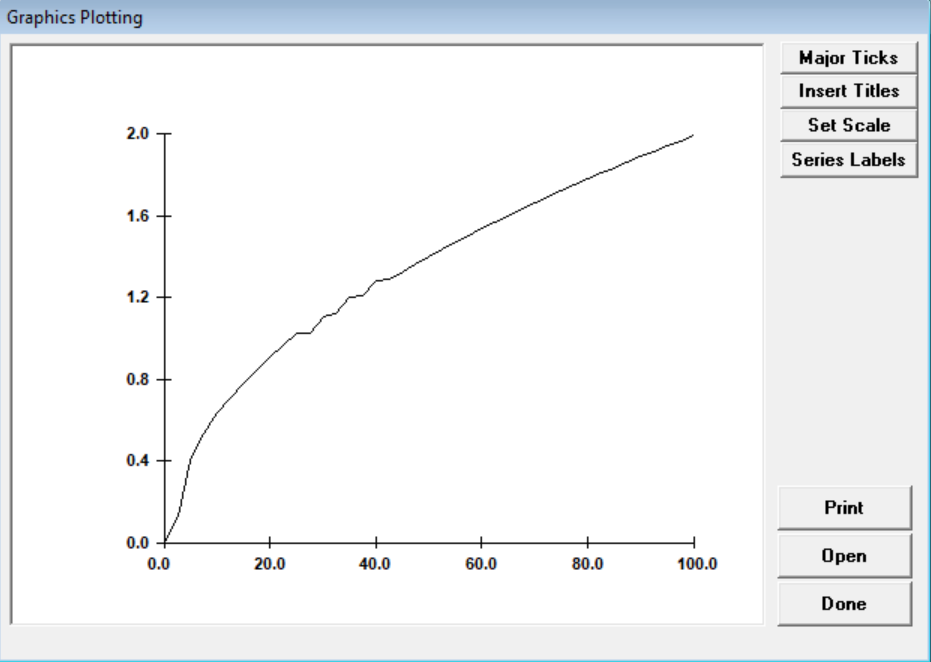 Figure 2: The Rating Curve Generated by VT/PSUHM During the latter half of November, the team has been focusing on making necessary corrections to the project report and completing the final draft submission for the conclusion of the semester. To address comments made on the quarterly report, we corrected formatting issues, implemented more calculations and analytical content, as well as enhancing tables and figures. A calculation that needs to be implented is the peak flow. To calculate the peak flow, a model in HMS needed to be run. The peak flow caused by Shabakunk Creek, as well as the peak flow caused by the building footprint itself are going to determine the hydrologic components of our design. Simulations were run in HEC-HMS for a 100-, 10-, and 2-year storm event. In order to determine the impact of development, a simulation was run for the building footprint for both pre- and post-construction conditions. The curve number for pre-conditions was 75 while the curve number post-construction was 99. The table ( Figure 1) below shows the resulting peak flows that our HMS simulation calculated. In addition, we were advised to incorporate visual models and tables representing our cost estimates, rather then relying on strictly a written format. Figures 2 and 3 displayed below, the call-out map of TCNJ and the Fema flood map, are two examples of figures that were adjusted and installed into the project report to help achieve a thorough and successful documentation of our design project elements and details. 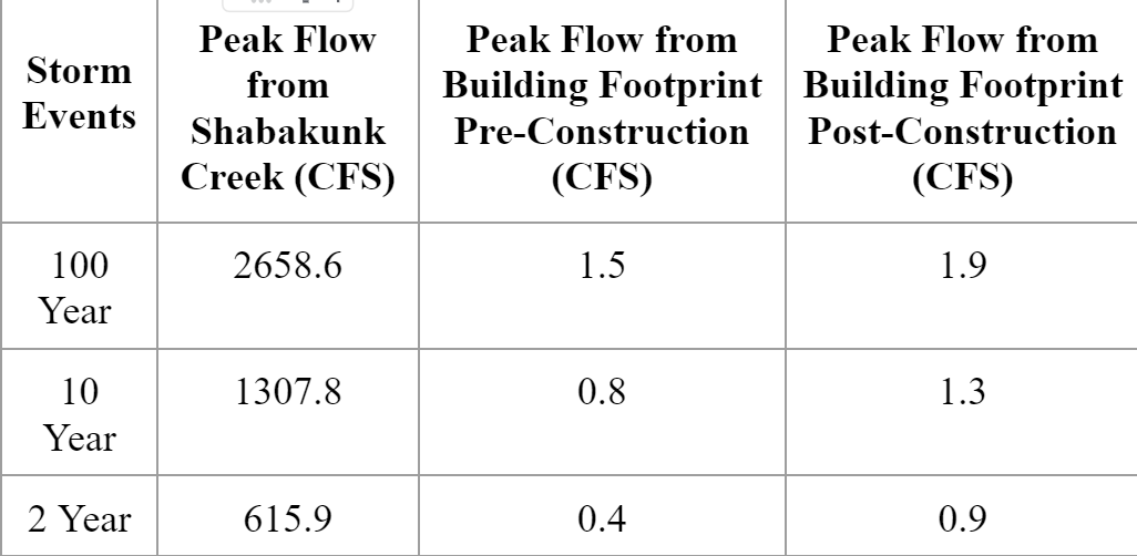 Figure 1: HMS-HEC Outputs of Peak Flow 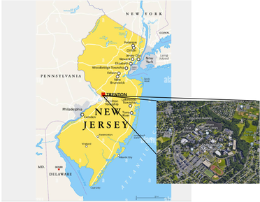 Figure 2: Callout Map of TCNJ 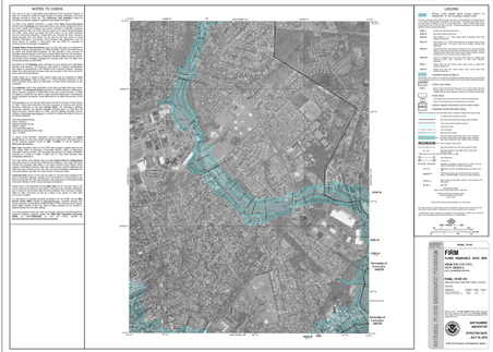 Figure 3: FEMA Flood Map
Utilizing the software program HEC- HMS, the hydrologic team conducted a simulation to determine the hydraulic peak flow caused by Shabakunk Creek. Within the simulation, a watershed area was created, and the model was run by inputting National Weather Service rainfall data from a 100-year storm event (Figure 1). The peak flow was calculated to be 1386.8 cubic feet per second. These outputs are exemplified in Figure 2. The next step for the hydrologic team will be to calculate the peak flow caused by the placement of the dormitory building. Once that value is determined, the storm water basins can be designed for the project. 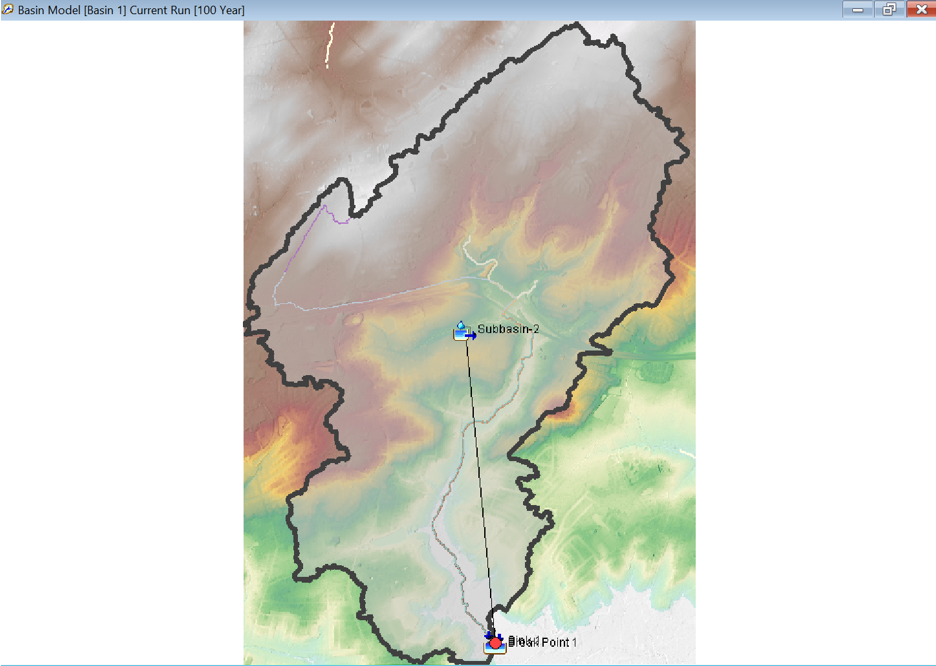 Figure 1: HMS Model of Watershed Area and Sub-basin 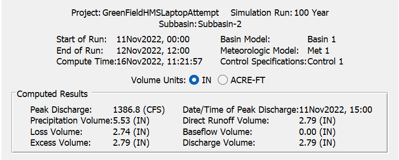 Figure 2: Table of Results from HMS Program. It shows Peak Flow for a 100 Year Storm Event.
The team has concluded the Alternative Designs presentation and received positive feedback from the advisors. The slideshow presentation is displayed in Figure 1. The hydrology team calculated were the curve numbers for locations Lot 4 and Green Lane Field. The curve number calculated for Lot 4 is 97, which is represented in Figure 2. This is a standard curve number for this area since the surface is a paved parking lot. The curve number calculated for Green Field is 74, which is represented in Figure 3. Based on this curve number, it was determined the grass area is in a fair condition. In addition to presenting the alternative design presentation and the curve number calculations, the team also completed the quarterly report. The goal for the next month will be to obtain feedback, fix the quarterly report, and to calculate the peak flow of the nearby creek. Figure 1: Slideshow of Alternative Designs Presentation 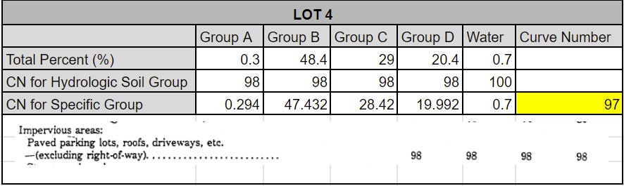 Figure 2: Curve Number Calculations for Lot 4 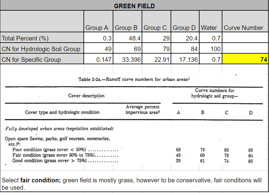 Figure 3: Curve Number Calculations for Green Lane Field
The team is working together to finalize our alternative designs that will be comprised of the main design elements and constraints that have been evaluated thus far into project development. It was decided to allocate our alternative designs into two main alternatives, consisting of different locations for our dormitory building design, and then magnifying focus further on multiple alternative sub-designs based on each location. The best possible locations that were considered within campus consist of the building area for the Travers and Wolfe towers, the area for Townhouses West, Green Lane Fields, and TCNJ Parking Lot 4. Developing a buildable area for Travers and Wolfe, along with Townhouses West, would be the most expensive locations to place our dormitory building due to necessary demolition of the preexisting structures in those areas. Furthermore, a dormitory designed in these areas would require for the building to implement a surplus amount of students to account for all removed housing from the demolished buildings, in addition to the evaluated number of students we need to consider due to the rising student enrollment. As a result, we decided the two best locations should be decided between Green Lane Field or Parking Lot 4. As for the sub-designs, alternatives for both locations will consist of differing building shapes and sizes. In addition to building shapes, another sub-alternative design for Green Lane Field, specifically, will be different types of basins that will be utilized to address drainage and flooding issues. For Parking Lot 4, further sub-alternative designs will focus on method for the relocation of any removed parking spaces due to the construction of the dormitory building. Figures 1 and 2 display the site plans for each location that also include depictions of the building shape sub-designs. The team is working efficiently to finalize these alternative designs and to begin preparations for our alternative designs and constraints presentation! 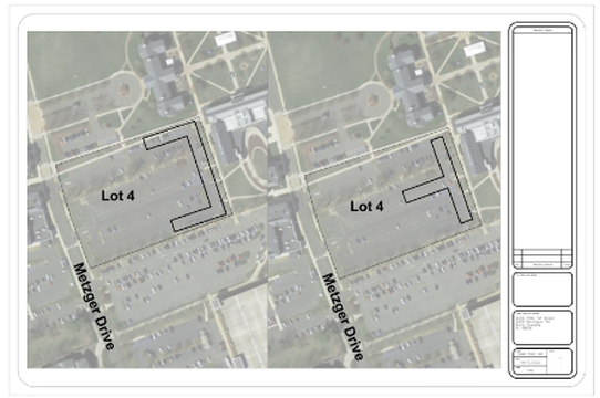 Figure 1: Lot 4 Site Plan with Sub Design 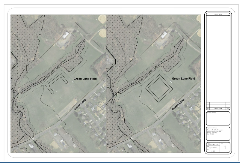 Figure 2: Green Lane Field Site Plan with Sub Designs
We are constructing our site plans using Civil 3D. Figure 1 exemplifies the site plan. We are currently coming up with different alternative projects using different locations and types of projects. We started calculating how many new students TCNJ will be adding to the school. After our calculations and researching important documents ,such as TCNJ Transformation 2.0, we were able to come up with the idea that there will be about 600 students being added. Therefore, we will be constructing a dormitory that will account for about 650 or more students. We are starting to compare the hydraulic analysis of Green Field to see where the best locations of our building would be. For the structural component we are deciding the dimensions of the dormitory and discussing if we want to construct the building with steel or concrete. A goal for the upcoming month is to finalize the alternative designs and pick a specific location on Green Field for our building! 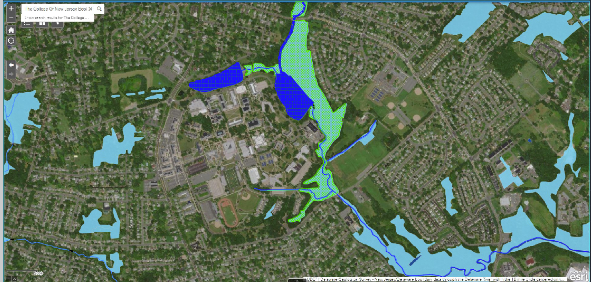 Figure 1: Site Plan made in Civil 3D
The first thing completed this month was our Project Proposal Presentation. We had our first meeting with our advisors. We are beginning the hydrologic analysis of the site by delineating a watershed area in stream stats (Figure 1) and gathering data from the web soil survey (Figure 2). We went over some goals for our group and the project. In addition, went over other possible locations around The College of New Jersey and in other locations in Ewing, New Jersey. Overall, the group decided it would be best to use Green Field for the dormitory. It will be a great addition to the campus and will open the campus to the community! 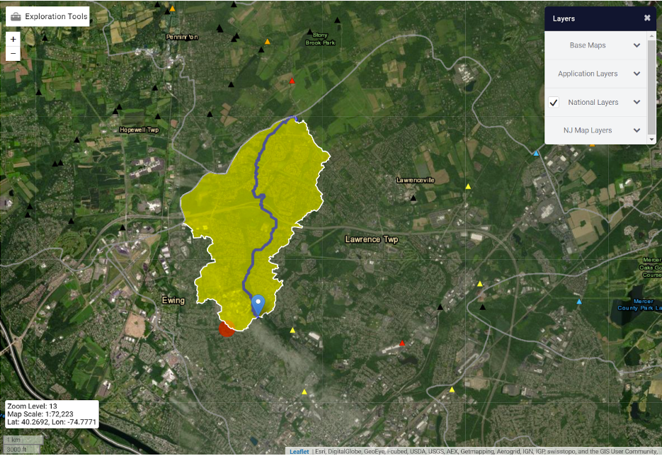 Figure 1: Watershed from Stream Stats 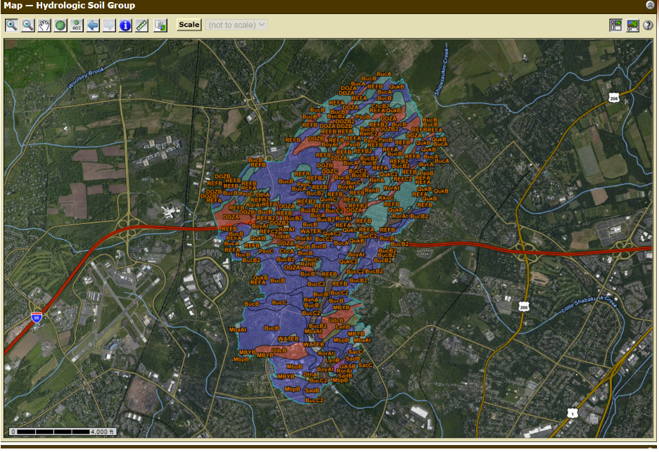 Figure 2: Hydrologic Soil Groups in the Watershed from Web Soil Survey
|
CategoriesArchives
April 2023
|
 RSS Feed
