Structural Team UpdateThe structural design team, consisting of Alexa Karpus and Tyler Morelli, is in the final stages of completing the structural design of the Green Lane Field dormitory building. The design process consisted of the development of a detailed floorplan and steel frame outline in addition to a structural design and analysis spreadsheet. Prior to the iterative process of designing concrete slab, metal deck, beams, girders, and columns, it was necessary for the team to construct the steel frame and floor plan in order to properly identify all unique structural members and any applicable design dead and live loads. The finalized AutoCAD drawing of the floorplan with the placement of the columns, beams, and girders is outlined in figure 1. 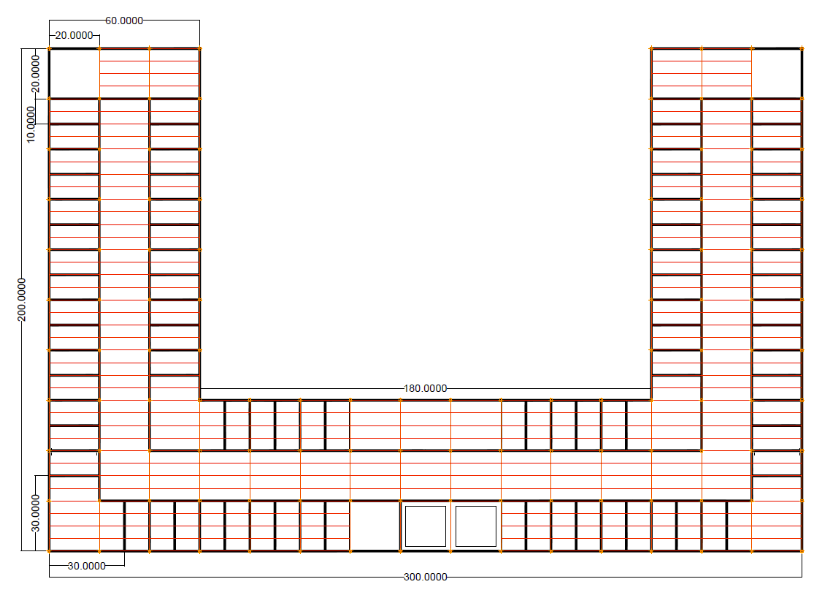 Figure 1: Finalized Floorplan and Steel Frame Plan of the Dormitory This floorplan represents where the columns, beams, and girders would be. After the frame plan was finalized, we were able to move onto the design work of the individual components. To design the individual components, we constructed an excel spreadsheet so it would be more efficient. We coded the spreadsheet to automatically update the entire design if something was altered. This made the design process easier. With this spreadsheet, we were able to design the slab, beams, shear connections, girders, and the columns. This is represented in figure 2. 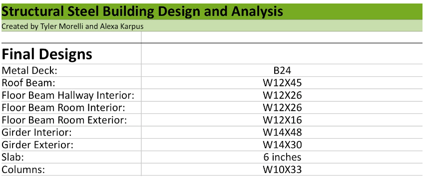 Figure 2: Table of the Design Selections For the next month, our goal is to calculate the horizontal loads due to the rain, wind, and snow. We will then need to analyze the designs and confirm they are sufficient. If they are not sufficient, we will be adjusting the designs accordingly. Water Resource TeamBasin Design The final design for the stormwater detention basin was completed using a computer software. The basin size was calculated and an outlet structure configuration was designed. The outlet structure includes designs for a 2-year, 10-year, and 100-year storm event. For the 2-year storm a circular orifice was designed, for the 10-year storm a rectangular orifice was designed, and for the 100-year storm a grate inlet was designed for the top of the rise box. Figure 3 shows the final hydrograph for a 100-year storm event with this design. Figure 4 shows the size and dimensions of the outlet structure configuration. The basin will have a top diameter of 40 feet and a bottom diameter of 10 feet with a depth of 7 feet, which is displayed in Figure 5. 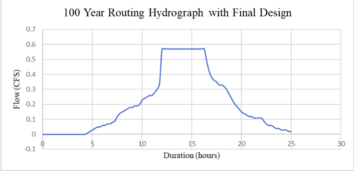 Figure 3: 100- Year Hydrograph for the Final Basin Design 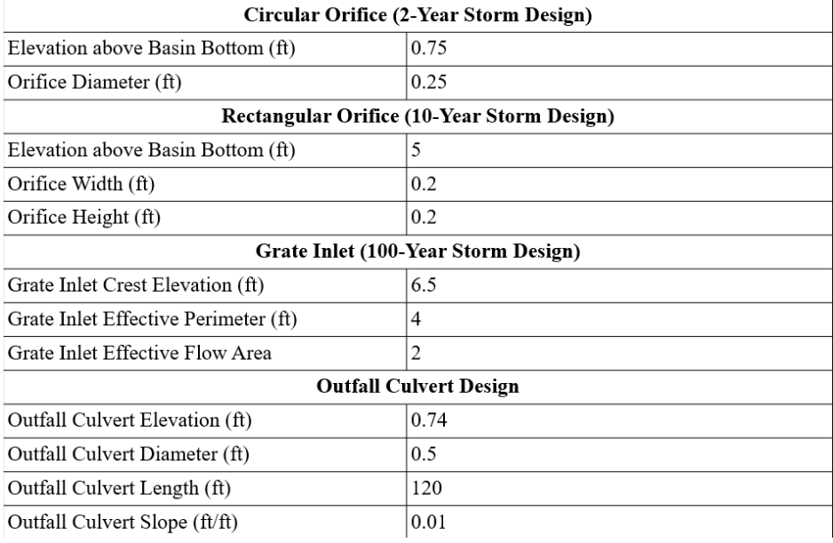 Figure 4: Table Showing the Outlet Structure Design Specifications for the Basin 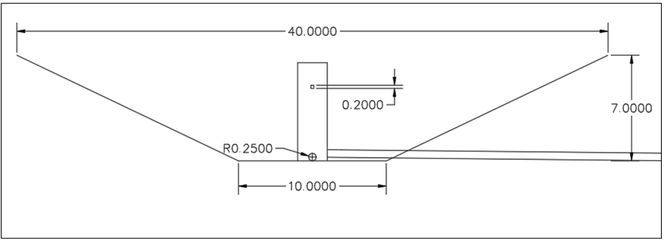 Figure 5: Cross-Section Layout of Storm Water Detention Basin Green Roof: The extensive green roof layers were designed as well as the green roof drainage system. The final configuration of the green roof consists of a combination of 8-inch and 3-inches pipes. The 8 inch parts consist of 460 feet of horizontal piping, 32 feet of vertical piping, four 90° elbows, one 45°elbow, one 8x8 45° junction, and two 8x3 reducers. The 3 inch parts consist of 60 feet of horizontal piping, 56 feet of vertical piping, four 90° elbows, two 3x3.1 1005T adapters, and two 3.1 JSR 1005T drains. All parts are made of cast iron (A888). Each drain is able to accommodate 17,400 square feet and the system can accommodate a peak flow of 1.9 cfs that was obtained from HEC-HMS. The total imbalance of the system is approximately 0.01% which provides insight on the accurateness of the system since the imbalance percentage cannot exceed 10%. Figure 6 represents the placement of the piping in the dormitory. 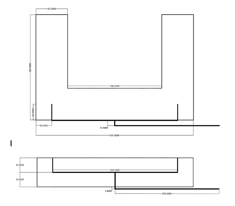 Figure 6: Location of the Pipes
0 Comments
|
CategoriesArchives
April 2023
|
 RSS Feed
